
Gerand pump test meter manufactured by Gerand Engineering Co. was required to supply Factory Mutual all drawings and independent laboratory test reports on all venturis in order to apply for Factory Mutual approval.
The Factory Mutual Approval was issued to Gerand Engineering Co. after the units were tested and met the Approval Standard – Class No. 1046 for Fire Pump Flowmeter Systems. Stated in this standard under II Description, Para. 4.2 Accuracy is that the system must meet an accuracy of ±2%, full scale deflection for the range of flows from 50% to 200% of the rated capacity of the pump for which it is used.
Factory Mutual annually conducts a stringent audit and inspection of all designs and parts used in the Fire Pump Test Meters. This inspection includes the reviewal of all quality control information we maintain on each part as well as a physical measurement of all dimensions of parts and random testing of the gauges.
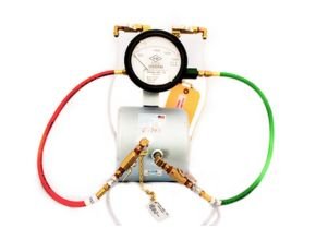
Attached to the meter with a brass chain is an oblong metal tag with the suggested piping diagram of the
system on one side, and the following operating instructions on the reverse side:
- Close system OSY valve “A”
- Open by-pass valve and “B” butterfly throttle valve
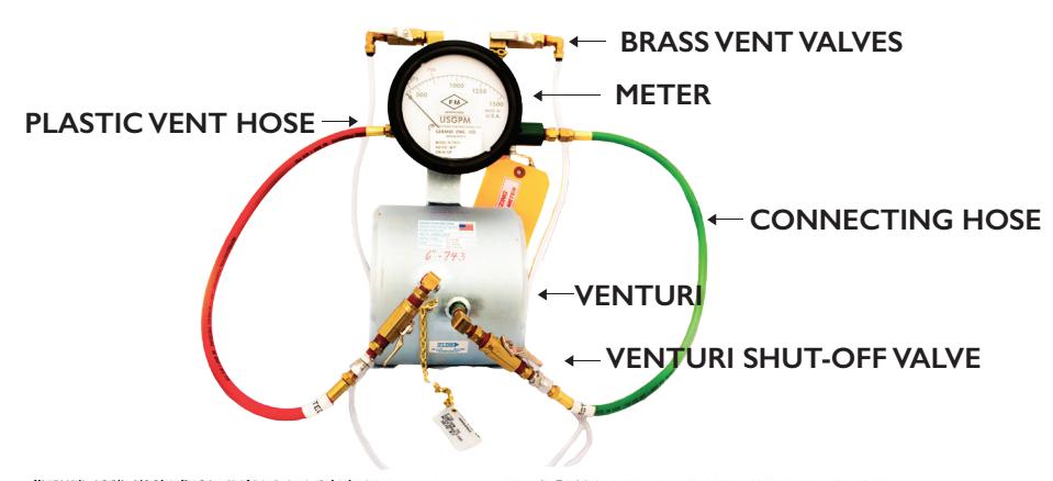
- Purge meter, located on venturi, as follows:
- Open station shut-off valves on venturi, and vent valves attached to meter. When a steady stream of water without air bubbles passes through the clear plastic hoses, the meter is purged of air.
- Close the vent valves after purging.
- Start the fire pump, and read meter in GPM.
- Refer to pump GPM requirement and adjust throttle valve to meet the requirement.
- After the test, open valve “A” and close the by-pass and “B” valves.
