

Thermal Mass Flowmeter VA 500
Contrary to the previously used bridge circuit the newly developed evaluation electronics of our flow sensor records all measured values digitally. This leads to better accuracy also in case of large measuring spans of 1:1000.

What are the advantages of our thermal mass flow meter technology?
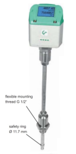
- Even under pressure, the thermal mass flow meter VA 500 is mounted by means of a standard 1/2“ ball valve. During mounting and dismounting the safety ring avoids an uncontrolled ejection of the probe which may be caused by the operating pressure.
- For the mounting into different pipe diameters VA 500 thermal mass flow meter is available in the following probe lengths: 120, 160, 220, 300, 400 mm. So the flow sensors a being mounted into existing pipelines with inner diameters of 1/2“ upwards. The exact positioning of the sensor in the middle of the pipe is granted by means of the engraved depth scale. The maximum mounting depth of thermal mass flow meter corresponds with the respective probe length. Example: VA 500 with probe length 220 mm has a maximum mounting depth of 220 mm.
- If there is no suitable measuring site with a 1/2“ ball valve present there are two simple possibilities to set up a measuring point :
- Weld-on a 1/2“ screw neck and screw on a 1/2“ ball valve
- Mount spot drilling collar incl. ball valve (see accessories)
- By means of the drilling jig, it is possible to drill under pressure through the 1/2“ ball valve into the existing pipeline. The drilling chips are collected in a filter. Then the probe can be mounted as described under point A.
- Due to the large measuring range of the probe even extreme requirements for the consumption measurement (high volume flow in small pipe diameters ) be met. The measuring range is depending on the pipe diameter

Special features of thermal mass flow meter VA 500:
-
- RS 485 interface, Modbus-RTU as a standard
-
- Option integrated display for m³/h and m³
-
- Usable from 1/2“ to 12“ (DN 300)
-
- Easy installation under pressure
-
- 4…20 mA analog output for m³/h resp. m³/min
-
- Pulse output for m³
-
- Inner diameter adjustable via keypad
-
- Consumption counter resettable
- Adjustable values at the display of the flow sensor: Reference conditions, °C and mbar, 4…20 mA scaling, pulse weight
Technical data VA 500 thermal mass flow meter
- Parameters: m³/h, l/min (1000 mbar, 20°C) in case of compressed air resp. Nm³/h,
Nl/min (1013 mbar, 0°C) in case of gases - Units adjustable via keys at display: m³/h, m³/min, l/min, l/s, ft/min, cfm, m/s, kg/h, kg/min
- Adjustable via keypad : Diameter for volume flow calculation, counter resettable
- Meas. principle: calorimetric measurement
- Sensor: a Thermal mass flow sensor
- Meas. medium: air, gases
- Sas types adjustable via external devices 400, DS 500, PI 500: air, nitrogen, argon, nitrous oxide, CO2, oxygen
- Meas. range: see table measuring ranges page 80
- Accuracy :
- ± 1.5 % of m.v. ± 0.3 % of f.s.on request
- ± 1.0 % of m.v. ± 0.3 % of f.s.
- Operating temp.: -30…110 °C probe tube -30…80 °C housing
- Operating pressure: up to 50 bar
- Digital output: RS 458 interface, Modbus RTU, M-Bus (optionally)
- Analog output: 4…20 mA for m³/h resp. l/min; on request : scaling for cfm,m³/min, l/min, l/s, ft/min, m/s
- Pulse output: 1 pulse per m³ resp. per liter galvanically separated
- Power supply: 18…36 VDC, 5 W
- Housing: polycarbonate (IP 65)
- Probe tube: stainless steel, 1.4301 mounting lengths 220 mm, Ø 10 mm
- Mounting thread: G 1/2“

| Info : marketing@wmablog.com |