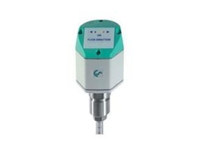
CS Instrument Thermal Flow Switch Model VA 409

VA 409 Flow direction switch for compressed air systems
The thermal flow direction switch VA 409 with direction indication serves for determination of the flow direction of compressed air and gases, especially in closed circular pipelines.
By means of VA 409 with flow direction indication, the flow direction of the compressed air can be determined quickly and safely. Compared with the former mechanical paddle flow switches VA 409 is able to detect even the smallest changes in the flow direction quickly and without any mechanical movement.
The direction information in form of a potential-free contact (normally closed max. 60 VDC, 0.5 A) is transferred to the consumption sensors VA 500/ VA 520 or to a separate building management system (mbs). Two LEDs show the flow direction.
In connection with 2 consumption sensors VA 500/ VA 520 incoming and outflowing compressed air in closed circular pipelines can be measured precisely.
Special features of the flow direction switch VA 409
- Compact, small design – for use in machines, behind the maintenance unit on the
final consumers - Screw-in thread for easy installation in existing pipelines due to integrated measuring
bloc , Sizes : ¼”, ½” ¾”, 1″ 1 ¼” , 1 ½” and 2″ - Integrated flow straighteners (no inlet runs necessary)
- Integrated display with a presentation of 2 values
- Flow & Consumption,
- Speed & Temperature
- Operation via integrated keyboard
- Units selection, freely selectable : m³/h, m³/min, l/min, l/s, kg/h, kg/min, g/s, lb/min, lb/h
Cfm, m/s,ft/min
- Units selection, freely selectable : m³/h, m³/min, l/min, l/s, kg/h, kg/min, g/s, lb/min, lb/h
- Digital interfaces
- Modbus RTU (RS485)
- Ethernet
- MBus
- Analog interfaces
- 4 – .20mA
- Pulse output galv. insulated.
- Pressure measurement (optional)
Specification
|
Detection range recognition flow direction
|
< 0.1 m/s referred to auf 20 °C and 1000 mbar
|
|
Measuring principle
|
calorimetric measurement
|
| Sensor | Pt 30/ Pt 700/ Pt 330 |
| Measuring medium | Air, gases |
| Operating temp. |
0…50 °C probe tube
|
| -20…70 °C housing | |
| Operating pressure | up to 16 bar |
| Power supply | 24 VDC, 40 mA |
| Power input | Max. 80 mA to 24 VDC |
| Protection class | IP 54 |
| EMV | acc. to DIN EN 61326 |
| Connection |
2 x M12, 5-pole, plug A and
plug B
|
|
2 potential-free contacts
|
2 x U max. 60 VDC, l max 0,5 A (normally closed); on request: Normally open
|
| Housing |
Polycarbonate
|
| Probe tube |
stainless steel, 1,4301, length 160 mm, Ø 10 mm, safety ring Ø 11.5 mm, longer probes on request
|
| Mounting thread | G 1/2“ |
| Diameter housing | 65 mm |
| Flow direction | 2 LEDs |

