

Mass Flow Controller/Mass Flow Meter With Indicator
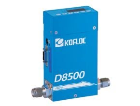
MODEL D8500 SERIES
This mass flow controller/meter driven by a 24 VDC power supply has been developed as successor to the MODEL 8300. The view point change function of the display unit and the pattern setting function are unique to this model, and noise resistance has been improved dramatically. A sister model with a detachable display and setting unit is also available.
Features :
• The high-lift actuator allows this compact model to control a large flow rate.
• Equipped with a display and setting unit, this model can be operated by a 24 VDC power supply
• The RS232C/RS485 communication function and integration function are provided as standard equpment.
• The 14-bit converter permits display and operation in 4-1/2 digits.
• Control of the flow rate of inflammable gas is possible, because the heat generating part of the sensor is not exposed to gas.
• There are no limitations on the mounting position that may be employed
• In addition to SV setting, five other patterns can be set.
• Auto zero and auto close functions are also standars.
Standard Spesifications :
– Flow range (F.S.) (at N2 calibration conditions) : 50 SCCM-5 SLM
– Applicable gases (dry gas) : N2, air, O2, CO2, Ar, H2, He, etc.
– Sensor : Thermal mass flow sensor
– Valve actuator : Normally-closed solenoid valve actuator *7
– Valve type : Poppet valve *7
– Control System : a). Control/measurement range : 2-100% F.S.
b). Response : 0-100% F.S. or more within 2 sec. *1
0-bellow 10% F.S. within 4 sec. *
– Accuaracy : a). Flow accuracy : ±1.0%F.S. *2
b). Repeatability : ±0.75%F.S.
– Pressure : a). Proof pressure : 1000 kPa (G)
b). Allowable operating pressure : 500 kPa (G) or less
c). Operating differential pressure *7 : 50–300 kPa (G) => 100-300 kPa (G)
– Temperature : a). Allowable operating temperature : 5–45℃
b). Temperature characteristics : 0.2% F.S./℃
– Humidity : a). Allowable operating humidity : 10–90% (No condensation allowed)
– Leak : He leak rate : 1 × 10⁻⁸ Pa•m3/sec. or less *3
– Flow setting method : a). Digital : (1) Setting & display unit
(2) Communications
(3) Event input selection
b). Analog *7 : (1) 0–5 V (2) 4–20 mA (freely selectable)
– Flow rate output : a). Analog : (1) 0-5 V (2) 4-20 mA (interlocked with the above)
– Display : a). Display format : 7-segment 4-digit LED
b). Total flow :12 digits *4
c). Mounting direction :Changeable
d). Built-in/Separate :Built-in, separate 1 m, separate 3 m, separate 5 m
e). Status display LED : OK (within allowable range), ALM (alarm output interlock) OUT1 (event output 1 interlock), OUT2 (event output 2 interlock) SV (set flow), PV (instantaneous flow), TF (total flow) IF (mode setting)
– Other I/O functions : a). Event input : 3 × contact input
b). Alarm output : 1 × open collector output, Max. 35 V, 50 mA
c). Event output : 2 × open collector output Max. 35 V, 50 mA
d). Communications : RS-485, half-duplex, 9600 bps
– Power supply : a). Rating : 24 VDC, current consumption: 300 mA max.
b). Allowable supply voltage range : 21.6–26.4 VDC (Ripple: 5% or less)
– Mounting position : Not specified
– Applicable standards : RoHS and EN62326-1: 2006
– Materials of parts in contact with gases : SUS316, SUS316L, SUS430, FKM, PTFE, chloroprene rubber (option)
– Joint : 1/4 SWL, RC1/4, 1/4 VCR
– Weight : a). Built-in: Approx. 1000 g
b). Separate (excluding the cable): Approx. 1200 g (*6)